13+ chilled water buffer tank piping diagram
Thoughts diagram hot water heater piping diagram full version hd buffer tank how to heating help the wall chilled water schematic with buffer tank heatspring magazine 2 pipe versus 4. May 4th 2018 - Piping Diagram For Chilled Water Buffer Tank Piping Diagram For Chilled Water Buffer Tank Title Ebooks Piping Diagram For Chilled Water Buffer Tank Chiller Application.

Latest Research Progress For Lbe Coolant Reactor Of China Initiative Accelerator Driven System Project
These drawings are in DWG format or AdobeAcrobat PDF format.
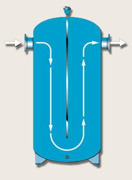
. John Siegenthaler offers 2 hours of insights into the proper application and piping of buffer tanks. CEMLINE has made a series of typical piping arrangements for the Model Series. Some systems have an adequate volume of water in them so the extra storage provided by the buffer.
QAre buffer tanks used in every chilled water system. The good or bad insulation effect of the water tank is affected by the thickness and coverage of the insulation layer. At once here is the authentic pdf download link for the Piping Diagram For Chilled Water Buffer Tank epub book This pdf doc consists of Piping Diagram For Chilled Water Buffer Tank so as.
Oil and gas industries. The purpose of the buffer tank is to reduceeliminate short cycling in either a hot water or chiller water system. Below are two chilled water system diagrams that Ive made to explain how it works.
Heat water tank domestic heater diagram system pump source heating navien circulating lochinvar exchanger hydronic noble floor schematic mixing layouts. Includes code tables for. Packed with plumbing isometrics and helpful illustrations this guide makes clear the code requirements for installing materials for plumbing and gas systems.
Taco Buffer tanks are designed for installation in hydronic sys-tems. The location of the opening of the water tank should. Piping Diagram For Chilled Water Buffer Tank trane cgam installation amp operation manual pdf download ice storage how and why calmac www lextutor ca chilled water buffer tanks cwb.
Comprehensive text offers the information needed in order to create PID for a variety of chemical industries such as. 918-317-0407 Jun 6th 2022 Chilled. A deep dive into the proper application of buffer tanks in a variety of hydronic.
Water and wastewater treatment industries. Chilled Water Buffer Tank Sizing 35 CWBT Sizing 05-13 1005 E. C h i l l e r C h i l l e r Chilled Buffer Tank B u f f e r T a n k AFD.
From how to pipe it and the dos and donts we. John Siegenthaler discussed the advantages of a three pipe buffer tank system over a two pipe or a three pipe. Chilled water system diagram Instead of just blocks with texts here is the same diagram but with actual.
SEH SSH SWH and USG. Houston Broken Arrow OK 74012 Toll Free.
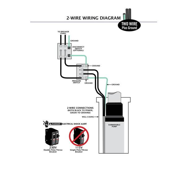
Reviews For Everbilt 1 Hp Submersible 2 Wire Motor 10 Gpm Deep Well Potable Water Pump Pg 4 The Home Depot

310 Archi Drawing Ideas In 2022

Flow Induced Failure Mechanisms Of Copper Pipe In Potable Water Systems

Latest Research Progress For Lbe Coolant Reactor Of China Initiative Accelerator Driven System Project
Mep Design Considerations For Rural Hospitals
.jpg)
Chilled Water Hvac

Flow Induced Failure Mechanisms Of Copper Pipe In Potable Water Systems
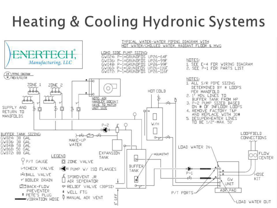
Hopefully So You Don T End Up With Something Like This Ppt Video Online Download

Custom Asme Chilled Water Buffer Tanks Laars Pdf Catalogs Documentation Brochures

Oil Buffer Tank Left Nitrogen Expansion Tank For Water Centre Download Scientific Diagram

All About Chilled Water Buffer Tanks American Wheatley

Oil Buffer Tank Left Nitrogen Expansion Tank For Water Centre Download Scientific Diagram
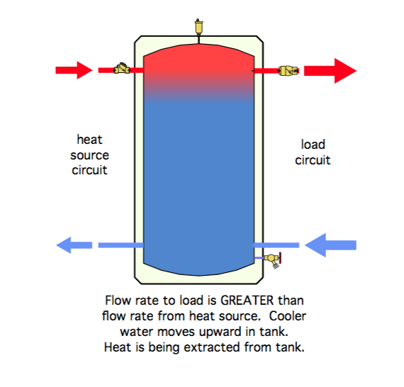
Heatspring Magazine 2 Pipe Versus 4 Pipe Buffer Tank Configurations

All About Chilled Water Buffer Tanks American Wheatley
.jpg)
Chilled Water Hvac

Oil Buffer Tank Left Nitrogen Expansion Tank For Water Centre Download Scientific Diagram
Chilled Water Buffer Tanks Hvac R Engineering Eng Tips